A close look at a 650nm laser diode
Because of a project involving a 7mW 650nm laser diode I had some diodes around, so I opened one up and took some close ups.
How a laser diode works: A quick overview.
Laser Components Laserdiode Red 650 nm 7 mW ADL-65075TA4
Laser diodes are semiconductor lasers, which already explains the name. At the heart of the component is a piece of layered semiconductor with the laserbeam being created in the pn-transition area. This area is a very thin layer in the semicondutor crystal, which is why the beam has different divergences in the x- and y-axis of the beam, contrary to lasers with round resonators, such as CO2- or ruby-lasers. The photons are excited directly by the electric current at the pn-transition area, which makes it relatively easy to modulate the beam by controlling the current. Therefore, laser diodes are driven by constant current circuits. Of course it is possible to use constant voltage sources, but since the diode heats up, its resistance changes during operation, causing the current to change. This current shift needs to be tightly controlled, or the diode might be destroyed.
A quick anecdote: In the project I mentioned I designed a constant current circuit, in the process of which I destroyed multiple laser diodes. They truly are fragile components. Luckily, low power diodes are relatively cheap.
The laser diode shown above has three leads: Vcc, GND, VR. Intuitively, Vcc is the supply voltage (2.5-6V) and GND is the voltage reference. VR is connected to GND via a potentiometer (or fixed resistor). According to the datasheet, this resistance is 3kOhm for maximum laser power and 17kOhm for minimum power. This makes the laserdiode relatively straight forward to control, given you have a controlled current source.
Opening up the diode
Opening the laser diode up was a pretty fiddly task, since it is a really small component: Only about 5mm in diameter. I used an abrasive disk for my dremel to carefully remove the cover of the diode. As you can see from the thumbnail, I could have been more careful, but it ended up working fine. The component only consists of two major components: The laser diode itself and the monitor photodiode:
The Laser diode itself is only a fraction of the size of the component (From now on, I’ll call the whole part “component” to prevent confusion) and is mounted on a heatsink, which itself it mounted on a pillar, which is connected to GND. The diode emits light in both directions, out of the laser window (usually quatz glass) and back into the monitor photodiode beneath it. This monitor photodiode is part of the internal automatic power control circuit (APL), which some of these components come with. The circuit diagram of the APL can be found in the datasheet. Its purpose is to sense how much light the diode emits, and regulate the current to reach the goal set by VR, making it a close loop system. Some cheap laser diodes come without this APL, which reduces cost, but turns the system into an open loop system without feedback.
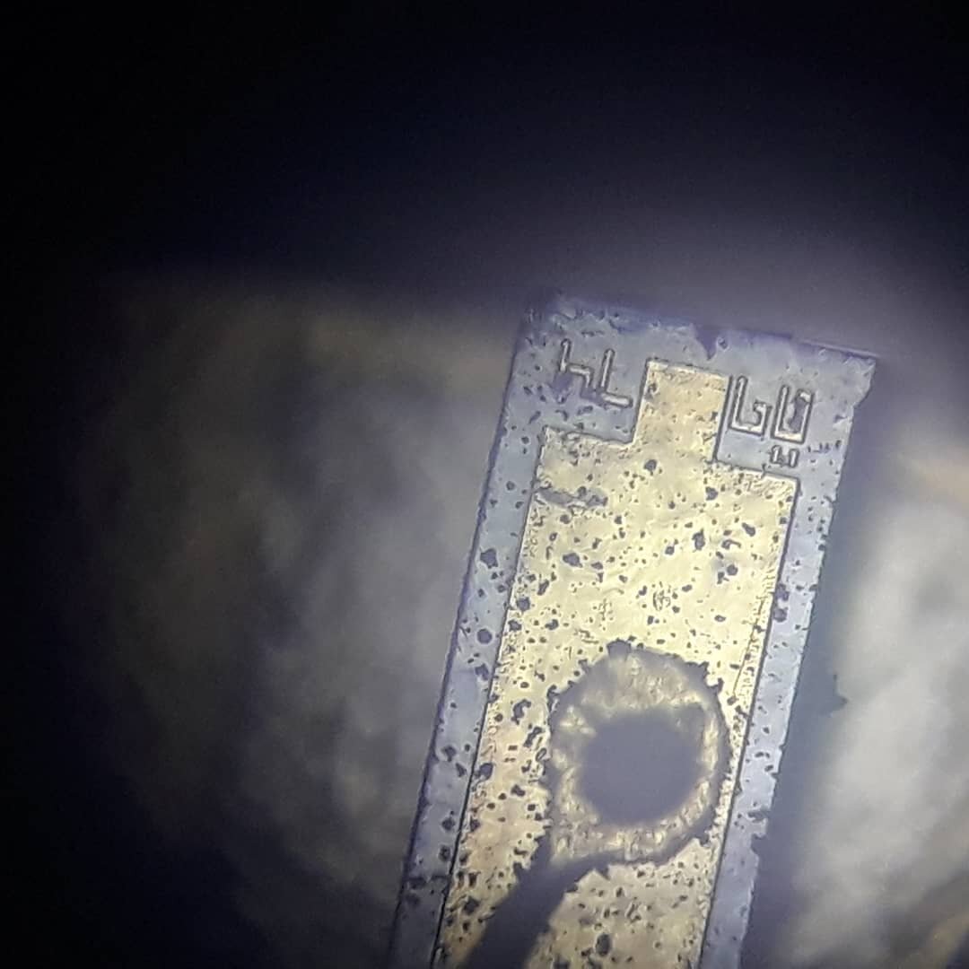
After I opened up the diode I used my microscope to make some pictures. They don’t really help to understand the parts better, but are interesting nonetheless:
This is the diode itself. You can see the little wire which is bonded to the top electrode of the diode. In the background (out of focus) you can see the substrate it is mounted on. The most interesting part are the markings, though. I can’t really say what they mean, but its interesting that the manufacturer would include these, especially since it is absolutely impossible to see them with bare eyes.
Here’s the diode again, but zoomed out a bit. It’s already impossible to decipher the markings at this magnification. But it is easier to see the general build-context of the laser diode.
Sadly, the monitor photodiode broke when I picked it off the base component, but here’s the main piece (It’s a wonder that I found this on my table since it is really small). I can’t say it for sure, but I’d guess that the grey part is the photo-diode and the golden part contains the rest of the APC.
And thats about it! As you can see, a laser diode is a relatively simple component, containing relatively few parts. Of course, the deeper you look into the physics behind the parts, the more complicated it gets.
I hope you found this article interesting!
As always, thanks for reading.


