Continuos wave diode pumped ruby laser
Although most ruby lasers are pulsed, it is possible to make continuos wave (cw) ruby lasers. In this article, I show you how I managed to build such a system using only a laser diode as the pump source, no arc lamps necessary!
Motivation and Background
Although I always wanted to make a ruby laser, I never had actually planned out a design for building one. This changed when I read a paper by Dr. Walter Luhs and Prof. Dr. B. Wellegehausen, showing a cw diode pumped ruby laser (the first one, infact!) and detailled instructions on how it performs.
Link to the paper published in 2019, DOI: 10.1364/OSAC.2.000184
So, after doing some research and also talking to Dr. Luhs, I actually managed to acquire the necessary optical components (mirrors and ruby crystal) for the laser. Thanks so much to Dr. Luhs for his enormous helpfulness!
Ruby laser theory
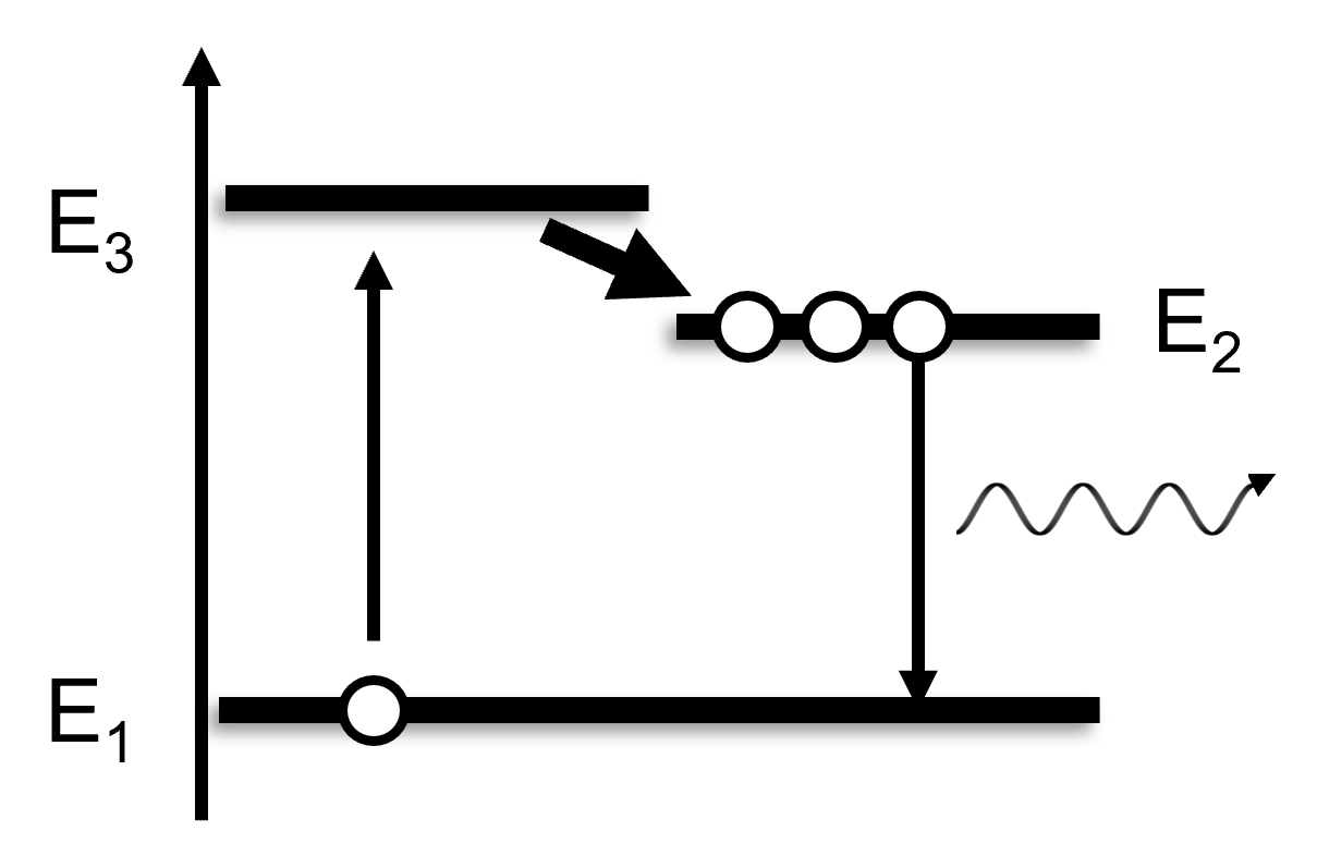
Operating a ruby laser requires a lot of pump energy. This is because the Cr3+ Ions of the ruby crystal (technically, ruby is a Cr doted aluminium oxide crystal) utilize a Three-Level-System.
Schematic of a Three-Level-System. For ruby, the lifetime of E3 is about 1e-9s (1 ns), whilst E2 has a lifetime of 3.2ms, which is about 3 million times longer.
If an electron using this system is excited, it gets transferred to E3 and almost immediately falls to E2. This stops it from falling back to E1 which would hinder laser action. It can then fall back to E1, emitting a photon (694nm) in the process. This happens after ~3.2ms by spontaneous emission or if it is hit by another photon of this wavelength. The latter is called stimulated emission and is the key to amplification of light (Laser = Light amplified by stimulated emission of radiation).
For amplification of light and therefore laser action to occur, a population inversion between E1 and E2 is necessary, so there must be more electrons in the excited state (E2) than in the ground state (E1). This means, ignoring E3 because of its very short lifespan, more than 50% of all the atoms in the ruby must be excited for any kind of laser output. Intensive pumping of the crystal is therefore necessary, which usually is done by high power flashlamps. In order to deliver these kinds of optical intensities continually, mercury-vapor-lamps and high power argon lasers have been used, both of which are quite involved systems. Diode lasers however have never been used (until 2019) to continually pump ruby lasers.
Absorption spectrum of ruby (source DOI: 10.1109/TIM.2003.822010)
Looking at the absorption spectrum of ruby, 540nm and especially 405nm seem to be absorbed the most. Luckily, 405nm Laser diodes with output powers of up to 1W exist and are relatively cheap on ebay (as part of fluorescent display modules).
Experimental setup
Above you can see the setup of the laser system: In order to get high intensity laser light, we need to focus it down to a narrow spot. This is hard to achieve from a highly divergent beam (typical for laser diodes), so it needs to be collimated first. The focal point is set to be within the ruby crystal. This crystal is 5mm long, has a diameter of 3mm and has an AR-coating for 694nm on both sides. In order to get laser action, the pumpdiode and mirrors must be aligned correctly. The planar mirror however is far less critical, which is a result of the hemispheric resonator:
As long as the distance of the two mirrors is smaller than the radius of S2, a resonant path is possible no matter the rotation of S1 (within limits of course). Therefore, only S2 and the pumpfocus must be aligned. There are four criteria that need to be met:
Pumpfocus must be within the crystal, ideally in the middle: High pump intensity
The resonator length should be equal to or smaller than the radius of S2: Optical stability of the hemispheric resonator
The axes of symmetry of the pumpvolume and the modal volume must coincide: Sufficient gain of the Laser beam and optical stability
The pumpvolume must be smaller or equal to the modal volume: Sufficient gain of the laser beam
Criteria 1 and 2 are self-explanatory, but 3 and 4 are not. The following schematic might help to understand them:
The pumpvolume (light blue) is the volume within the laser crystal that is pumped by the source. The modal volume (dark blue) is the volume of the lasermode, it is defined by the position and radius of S2. Since only the atoms within the pumpvolume can provide gain, the modal volume must coincide fully with this volume. Any areas of the modal volume which are outside of the pumpvolume do not experience gain and can therefore not be part of the laserbeam. Therefore, it is critical to make the modal volume coincide fully with the pumpvolume (criterion 3). This can only be the case if the pumpvolume is physically bigger than the modal volume.
In order to meet the four criteria for laser action, the following system was set up:
This design allows for linear translation of the pump diode and S2, which correlate with the position of the focal point and the resonator length. It is also possible to fine-tune the alignment of all the elements via fine-pitch screws. All of mechanical parts are homemade on my CNC-router and my metal lathe. I designed the mirrormounts to use magnets pulling them onto a kinematic base. This makes the mounts relatively compact and easily removable. The diode is cooled via a fan blowing air onto the aluminium holder and driven by a constant current source seating in wooden box. This box was lasercut on my CO2-Laser and has a current meter, an adjustment knob and mains socket to make the setup as compact and clean as possible. The setup is mounted on an optical breadboard sold by Thorlabs.
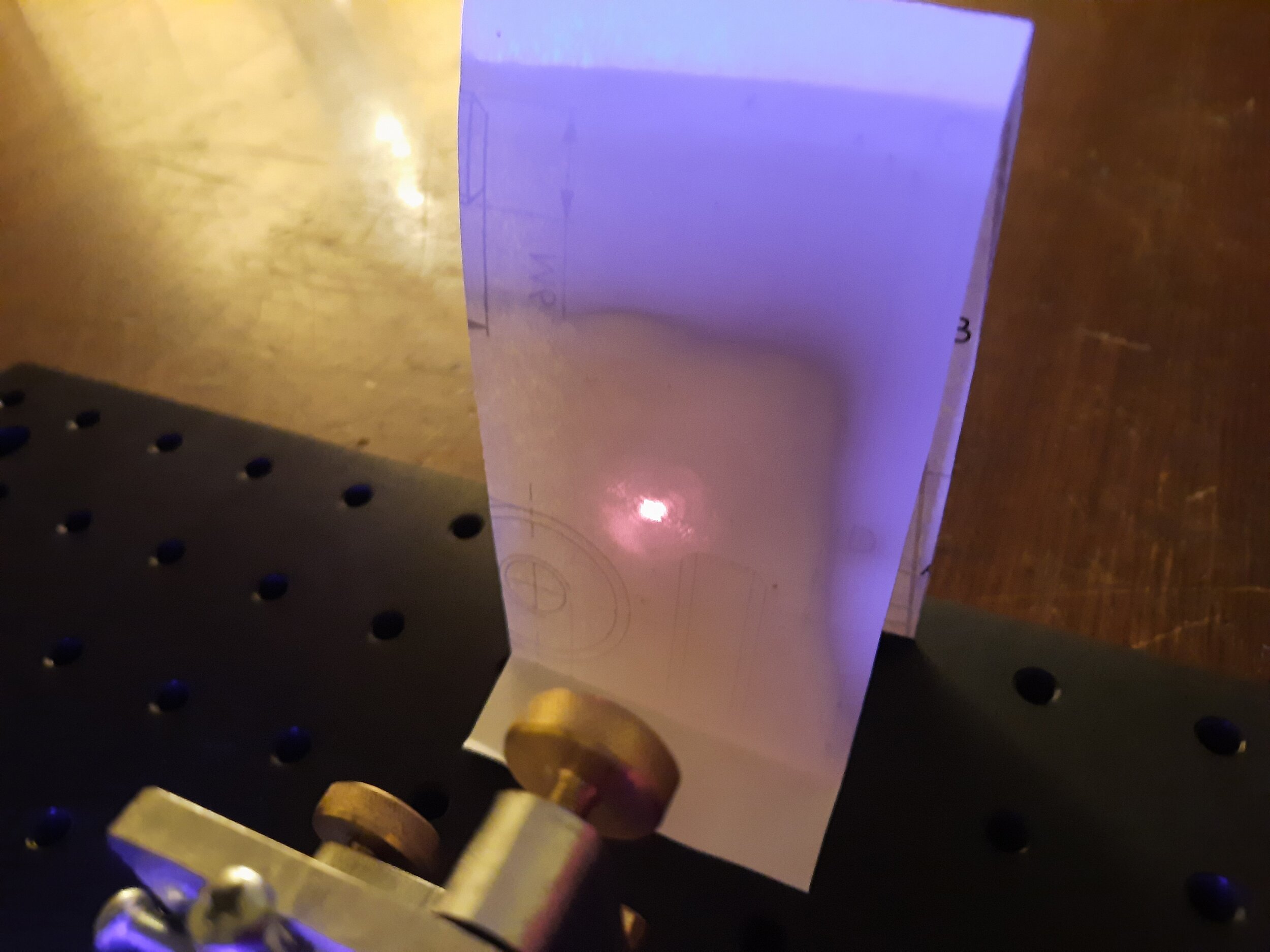
In the following pictures, you can see the laser in action!
An overview over the system. The spot created has a nice round shape.
The ruby is fluorescing vividly under the 405nm pumplight.
With the camera exposure turn way down, you can see the pump- and modal volume as one bright fluorescent track.
This picture is from a previous setup but it clearly shows the bigger pumpvolume in the middle and the smaller modal volume above it. Aligning S2 would move the modal volume.
Another quick note: Because some parts of the pumplight make it through the outcoupling mirror (S2), they can outshine the created 694nm beam and make it really hard to observe. To prevent this, I put an optical edge filter after S2, which filters out practically all of the 405nm light, but transmits a vast majority of the ruby laser light.
Because the whole setup is very touchy (due to the thin baseplate and the homebrew mirrormounts), it is a challenge to align it properly. Slightly leaning on the table can already destroy resonance. This actually once produced an interesting sideeffect: I leaned onto the table and the output beam was split in two beams. It seems that the resulting misalignment was so subtle, that rather than destroying resonance, it created a TEM01 mode. Sadly, I wasn’t able to reproduce this effect in order to take some pictures, but I am very happy to have finally seen a TEM mode in the wild.
Since I currently am not equipped to measure properties of the system such as pump-efficiency, beam quality, absolute output power, transient response, etc., I can only report on the pump-threshold, which was about 300mW. I hope to measure a few more properties at an optics lab in a few months, but these plans have not been verified yet.
UPDATE 16.02.2022: I have been able to measure the optical output power in lab at my university and got up to 43mW of laser output power at 1W input power. I am very happy with this result, considering that the original paper reached a maximum of 36mW.
Possible applications of this design depend on these properties, which is why I’ll refer to the original paper at this point. If you’re interested in this design, I’d definitely recommend reading it anyways, because it covers some of the topics above in more detail.
Thank you so much for reading and your interest in ruby lasers, stay creative and see you next time!
~N


