High power pulsed Nd:YAG Laser: Design and Experiments
One of the most used laser media in the industry today is Neodymium doped Yttrium Aluminium Garnet, or short Nd:YAG. Due to its high efficiency and good thermal conductivity it is used to make lasers of potentially very high output powers. In this article, I’ll show I made a pulsed Nd:YAG laser capable of piercing multiple razorblades at once.
Theory
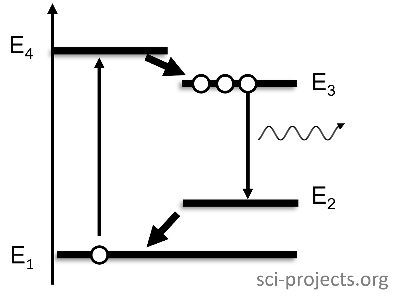
Nd:YAG lasers are four level lasers. This means that the laser atoms - in this case the trivalent Neodymium ions - go through four distinct energy levels for and during the lasing process. The picture below shows a typical four level system.
Four level lasers operate as follows: The pump energy (usually coming from high power flashlamps, arclamps or pump lasers) excites the electrons to E4. The electrons then reach E3 via a quick, radiationless transfer. This level is the upper laser level: A transfer to E2 will result in the emission of a photon of the energy E3-E2. However, to achieve laser action, this is not enough. For this, a population inversion between E2 and E3 must occur, so E3 must contain more electrons than E2. Only then will stimulated emission be the prevalent process and lasing can begin. For three level systems, high pump rates are necessary for enough electrons to reach the upper laser level sufficiently quick. However, four level systems have a trick up their sleeves: The fourth energy level E2 can quickly transfer its electrons to the ground level and therefore reduce the electrons necessary to keep up population inversion. This is why four level lasers, like Nd:YAG, are so much more efficient and practicable than three level lasers: They need much less energy to reach lasing threshold.
Another consideration, especially for laser designers, is the average fluorescent lifetime of the upper laser level because it sets the time limit after which the upper laser level will begin to depopulate fast. So, for pulsed lasers it is advisable to put all of the pump energy into the material before the lifetime is reached to maximize laser efficiency. In our case, this means that the pulselengths of the flashlamps will have to be around 230 μs, which is the fluorescent lifetime of Nd:YAG.
Laser design and implementation
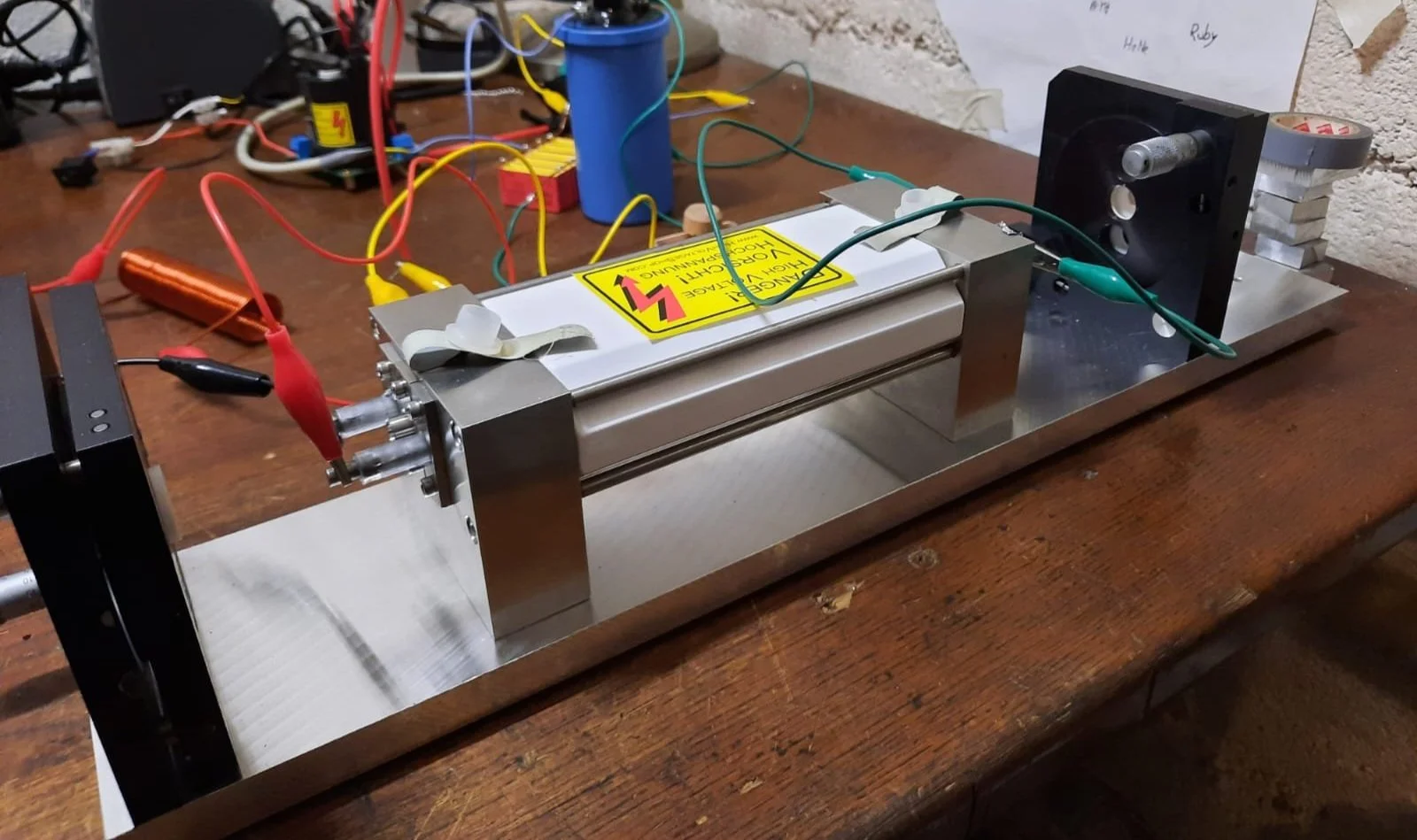
Since the main components of this laser system were bought in a bundle at an auction, the core design already is fixed: The laser consists of a plane - plane resonator, two flashlamps and a 180 mm long (6.3 mm diameter) Nd:YAG crystal. The crystal and flashlamps are inserted into a reflective ceramic chamber which maximizes the coupling of pumplight into the laseractive medium. One mirror is highly reflective for 1064 nm (HR) and the other one is about 50% reflective (output coupler = OC). Since the pump intensities are very high and the crystal is relatively long, the light amplification is extraordinarily high and low output reflectivities of 50% or possibly even less are necessary to provide the optical feedback for lasing.
The optical cavity is aligned using the procedure I described in this previous article. There is enough space between the mirrors to allow the insertion of a passive Q-Switch Cr4+:YAG crystal, see chapter Q-Switching. As you can see, the core design is very simple.
Experimental setup of the cavity.
Electrical design
Probably the most challenging part (at least for me) of this project was designing the power supply for the flashlamps. In order to understand what makes the power supply special, let us quickly look at how flashlamps, in this case Xenon-flashlamps work:
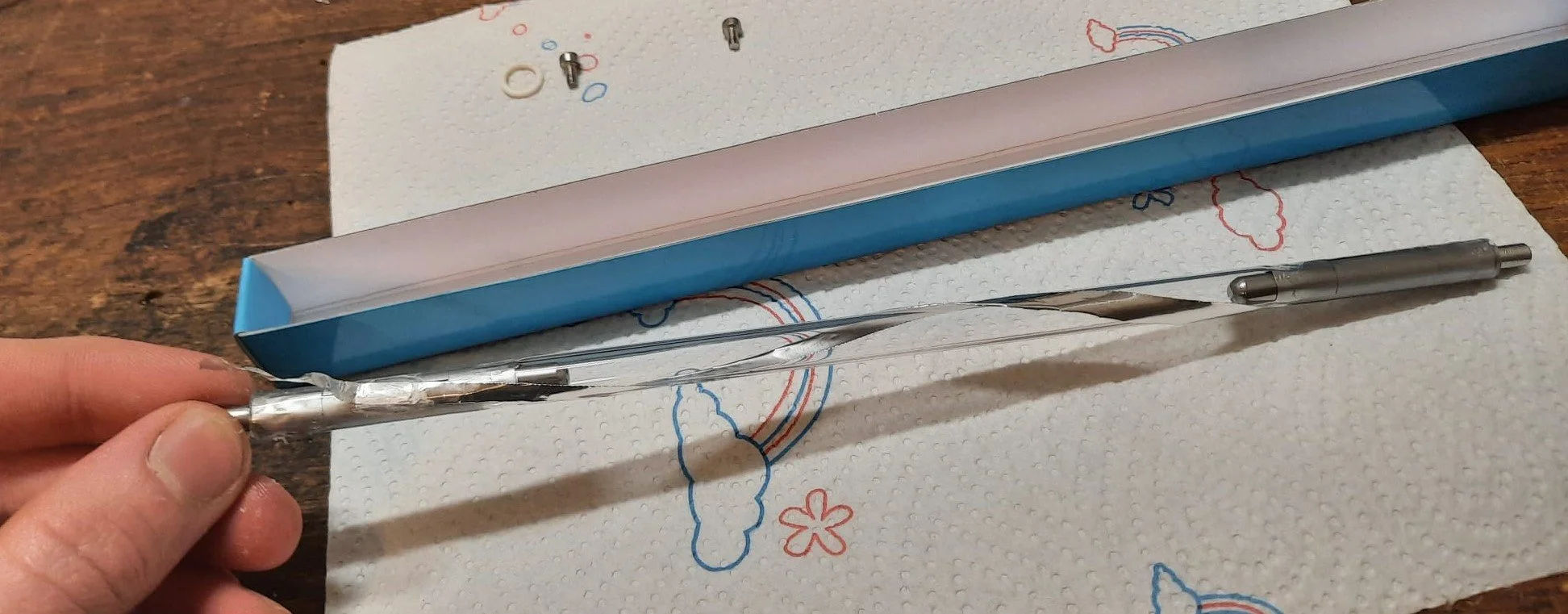
As you can see in the picture above, flashlamps are essentially sealed volumes containing noble gas. No current can flow between the electrodes since the gas is not conductive, even at voltages of several hundreds or even thousands of volts. However, this can be changed by introducing a short, high voltage pulse (10-20kV) into the trigger wire: Since the pulse has a high frequency, it capacitively couples through the dielectric glass envelope and ionizes the gas within. This causes the gas to suddenly become very conductive because the electrons - previously bound to the atoms - are now “ripped” off of them (= ionization) and thus free to move. Any voltage between the electrons now causes current to flow. Usually, this current is provided by high voltage capacitor banks since they can source massive amounts of currents (>1000 A) momentarily. These currents excite the noble gas and the flash occurs, emitting very high intensity light.
Warning: These capacitor banks usually are charged to many hundred of joules (at high voltages) and therefore exceedingly dangerous. Also, never stare into a flashlamp when it is pulsed - it may damage your vision permanently. Proceed with due caution if you want to build a system like this.
The triggering method described here is called external triggering because the pulsed is introduced externally. It is also possible to introduce the pulse by wiring a trigger transformer in series with the flashlamp, look up series triggering for more info. In my case, I wrapped a small strip of aluminium foil around the flashlamp, but a normal wire should also work well. Note that in the picture below I am only touching the electrode, touching the glass with your fingers should be avoided to prevent charring of any oil residues.
It is important to know that these flashlamps are designed to operate in pulsed mode. There are similar components available for continous wave operation, so-called arc lamps, which work similarly and may be used for continous wave Nd:YAG lasers but they are of no concern for this project.
To create the trigger pulse, I first used a Greinacher voltage doubler to convert 230V AC to 500V AC. The last capacitor of the doubler is discharged through an automotive ignition coil by a thyristor. This creates ~30kV pulses for the series triggering. The main capacitor bank is wired across the flashlamps - which are connected in series - at all times. It consists of 6 Unlytic UL33 film capacitors, with three sets of capacitors in parallel, each set consisting of two capacitors in series, resulting in 435 uF overall capacitance. Note that film capacitors are quite necessary for this application - electrolytic capacitors have insufficient internal resistance, making short pulses of 230 us impossible to achieve. This bank is charged to about 1200 V (therefore 313 J) by a microwave oven transformer (MOT) and a variable transformer. This voltage was chosen because it lies within the voltage rating of the capacitors and is enough to ignite the flashlamps. The AC voltage coming from the MOT is rectified using a diode (or rather, two in series). Here lies another pitfall: The diodes used must have a voltage rating of at least two times the AC voltage. This is because the fully charged capacitor bank will be at +V and the supply voltage will be -V in the negative cycle. This issue is simple to work around when recognized but it took me quite a lot of HV diodes to notice what was happening to them. Usind a full wave rectifier instead of a single diode would decrease charging times but since high repetition rates were not the goal of this project, I left it at that. If you want to know how diode rectification works, take a look at this article. You can see the overall schematic of the power supply below. Of course errors are possible, I am not an electrical engineer.
Again, if you want to reproduce this, proceed with caution: Line voltage and especially microwave oven transformers are very much capable of stopping your heart instantly. A safety precaution at least for the capacitor bank are bleeding resistors: Those are medium-high resistance resistors wired across the capacitors permanently so that the capacitor bank will discharge slowly on its own when left unattended.
If you look at the schematic above, you see another interesting peculiarity of the power supply: The pulse forming inductor. Since film capacitors have very low internal resistance, they allow massive current draws; enough to overwhelm even flashlamps. Also, to maximize laser efficiency, it is advisable to use the whole fluorescent lifetime window of the crystal. The task of the pulse forming inductor is therefore to stretch out the pulse to about 230 us. In my case, a homewound linear aircoil of about 20 uH worked fine. Using the following approximation, we get 280 us, which is a bit too high but still acceptable:
Together with the capacitors, the inductor makes up the pulse forming network (PFN) which is an essential part of pulsed laser power supplies.
Mechanical Setup
The optics and electronics are mounted inside a box consisting of extruded aluminium profiles. In order to keep dust and debris out of the system, it is closed off using aluminium laminated (Dibond) and acrylic sheets. The laser output window is a antireflective coated quartz window.
As you can see in the pictures above, the box is designed to be a standalone system: Just connect it to mains, turn up the variac until the capacitor voltage is sufficient and press the button on the top left to ignite the flashlamps. The box has handles attached to it since it is very heavy, about 25 kg.
System deployment
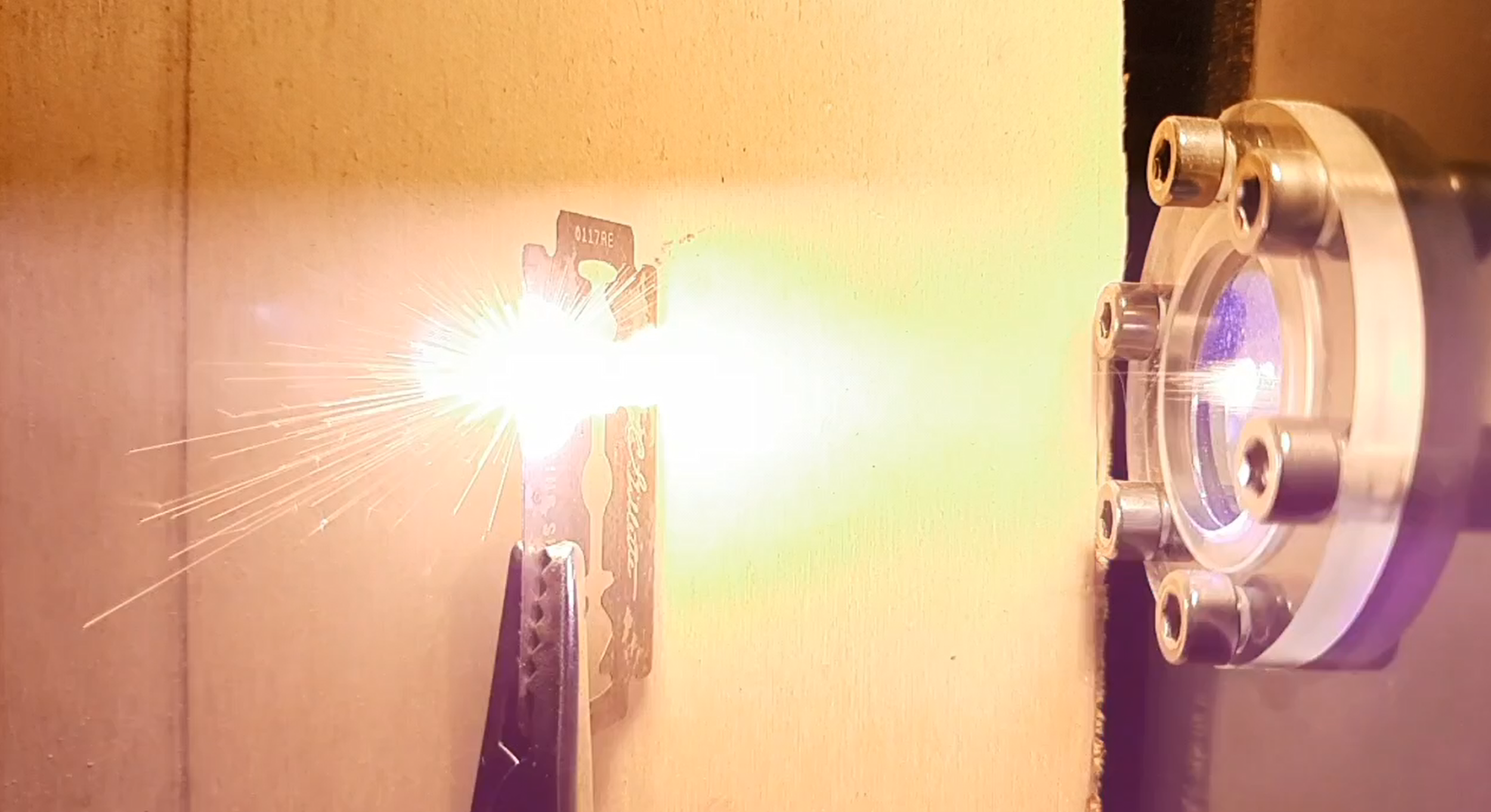
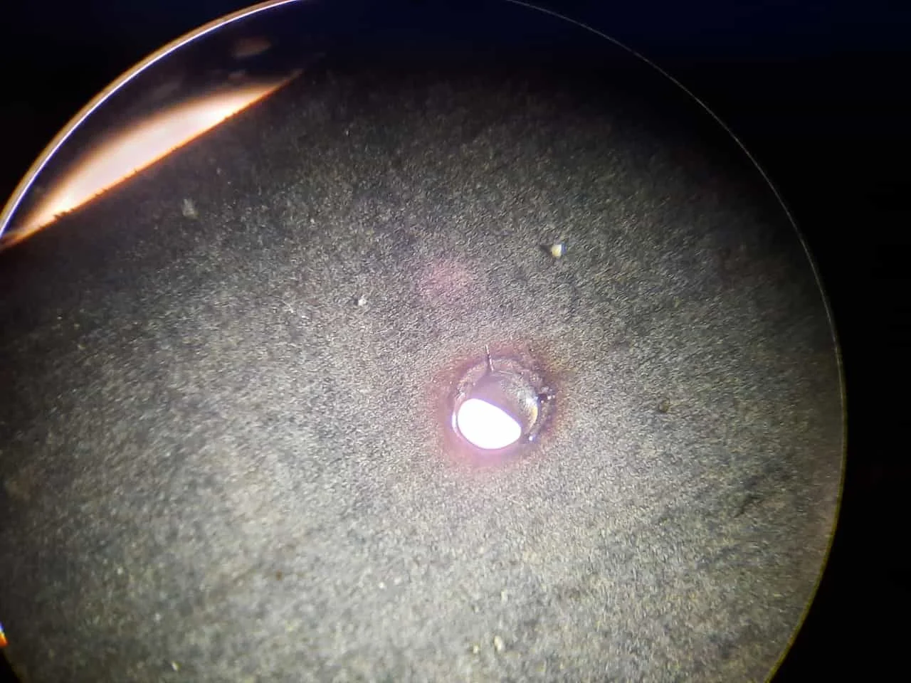
Due to the long crystal and high pump energies, the laser has very high output energies even though the repetition rate is very limited. It is capable of easily punching through multiple razorblades at once: I tested up to three and it went through all of them.
Test shot at a razorblade
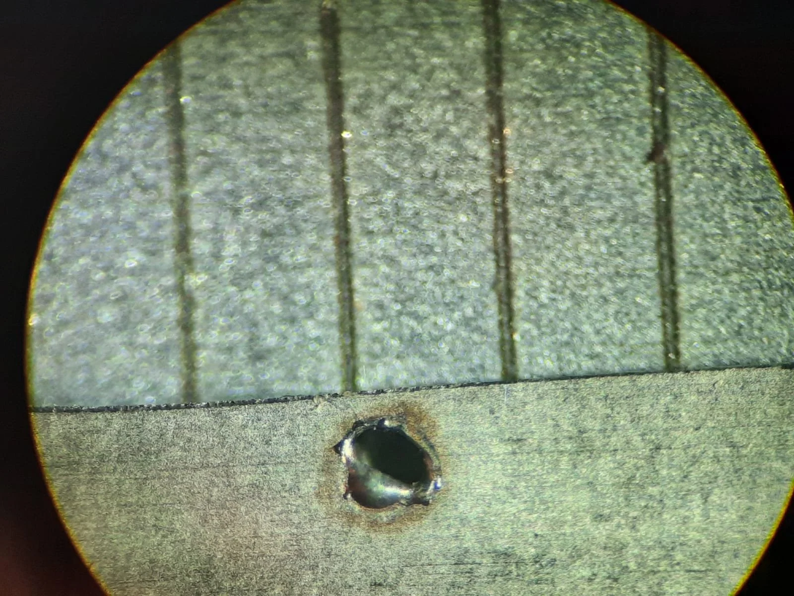
The hole diameter is about 0.4mm as you can see in the magnified pictures below. This of course depends on the focus. Since the output power is high even slightly out of focus shots will penetrate the razorblade, making the hole slightly bigger.
The lines in the picture above are the 1 mm marks of a caliper.
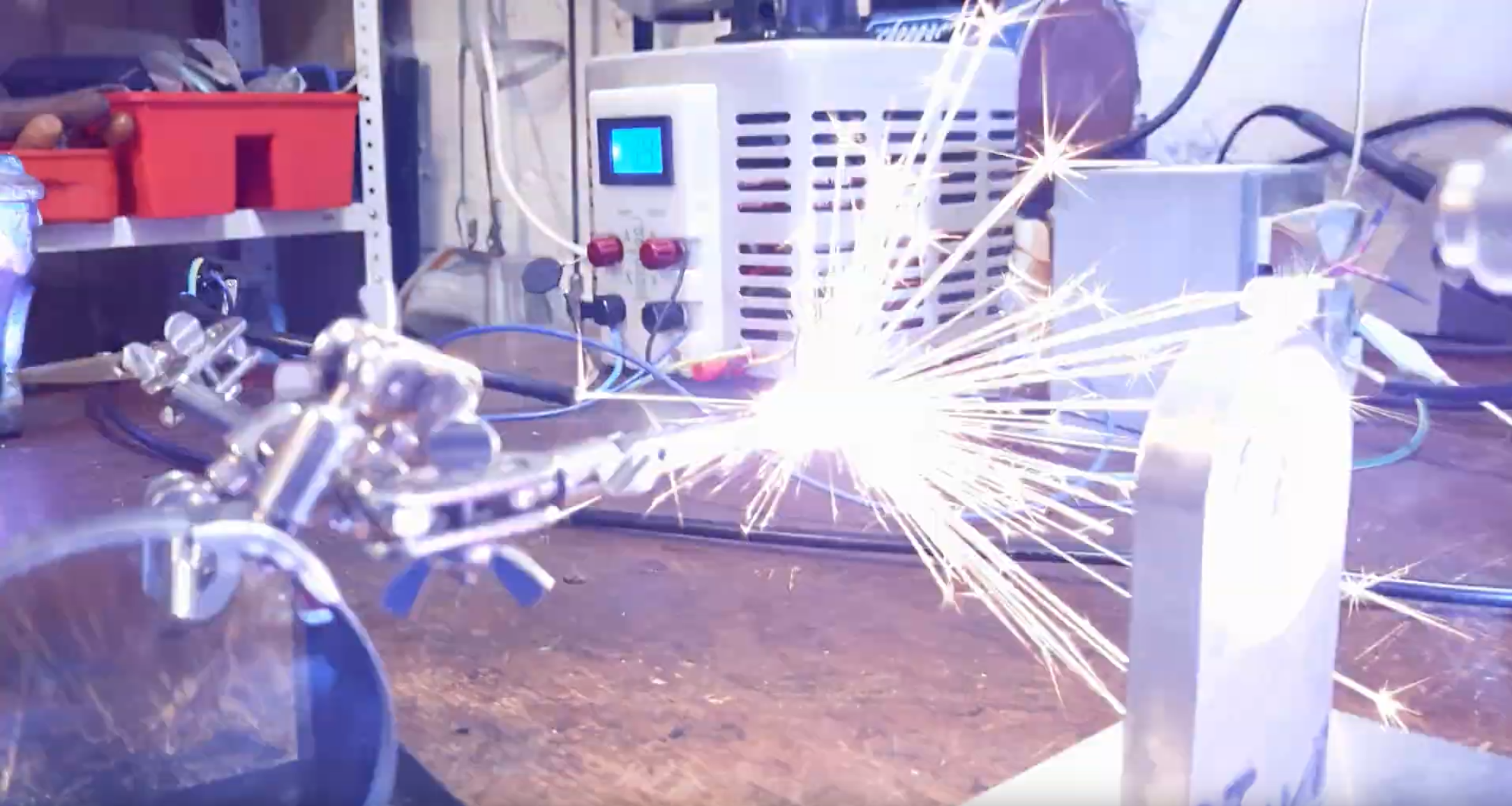
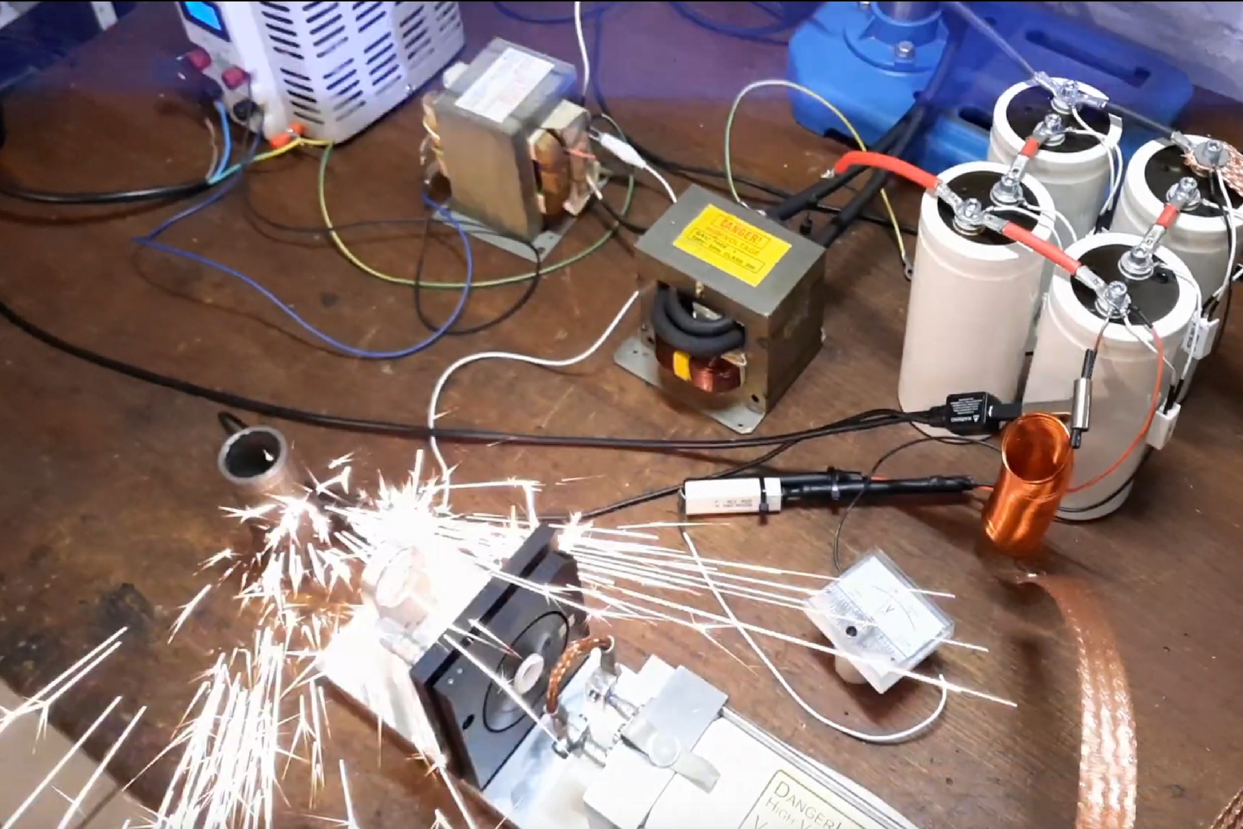
Focussing the laser on thicker steel sheets will produce a shower of sparks. The pictures below were taken when the setup was still experimenal but since the optical setup has not been altered they are representative of what the finished system can do.
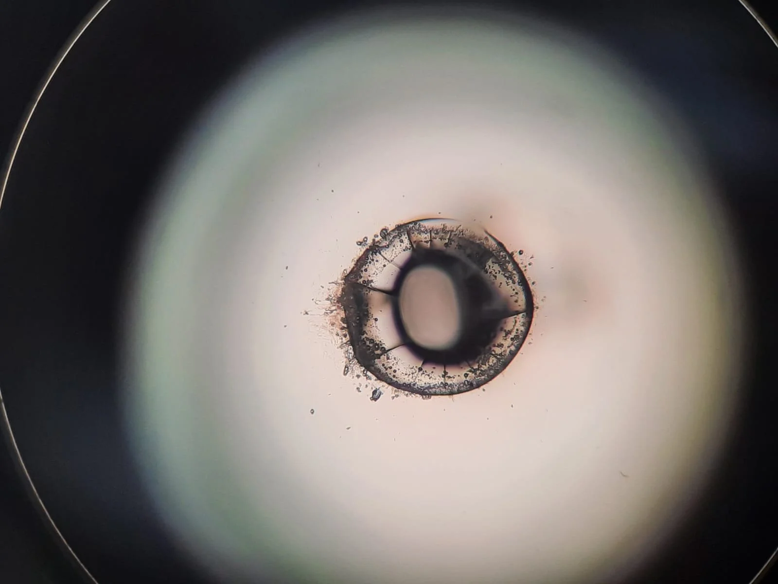
As you can see, the beam is very capable of drilling holes in metal, but I decided try something else: Drill a hole in glass. The picture below shows the result of that experiment. As the target I used a 1 mm thick microscope slide. The edges are bit “melty” and there seem to be some cracks at the edges probably due to the thermal stress of the sudden melting and resolidification but it definitely worked nonetheless.
Of course, a laser like this is not only capable of putting holes into perfectly fine objects, it should also be able to weld thin gauge material (like wires and sheet metal) together even though I have not tried that yet. This might make it possible to make custom thermocouples at home or spot weld sheet metals for other projects.
However, there something much more exciting (at least for me) that can be done with a system like this: Q-Switching.
Q-Switching
Q-Switching, also known as Gain Switching or Quality Switching, is a technique that enables extreme boosts in peak output power. To understand how it works, it is necessary to know that the lasing process is fueled by the population inversion within the laser medium. The higher the population inversion the higher the amplification and therefore output power. In turn, the population inversion is fueled by pumping the medium. Under normal operation, a kind of steady-state governed by the rate equations is reached: Pump power goes in, increasing the population inversion and output power goes out, depleting the population inversion.
But as soon as stimulated emission is not allowed to deplete the population inversion anymore, this steady state is disrupted: The pump will “fill up” the laser medium (considering the bucket-water metaphor depicted above) to levels that were not previously possible. This disruption can be achieved by hindering the laser process, e.g. by creating losses in the resonator. This reduces the quality (Q-Factor) of the resonator, which explains the name. Once the level of population inversion has risen high enough, the quality of the resonator can be suddenly increased. Because the population inversion and therefore amplification is much higher than usually possible, the resulting output power will be much bigger. High amplification also means high depletion rate of the population inversion so the pulselength is very short.
The switching of the quality can be done actively or passively. Active Q-Switching can be done by e.g. inserting polarization dependent losses using Pockels cells and high frequency drivers. Passive Q-Switching is usually done with saturable absorbers like dyes and crystals. These materials absorb light until the intensity rises to a specific level and then suddenly becomes transparent. Of course different laser wavelengths require different materials. In my case, I used Cr4+:YAG crystal because the setup is very simple: I just inserted the crystal in the resonator without any special alignment. Since the faces of the crystal are parallel, its alignment inside the resonator is not critical.
Since the base setup already is relatively powerful, the Q-Switched pulses have very high peak powers. The peak powers reached by the setup are high enough to showcase a very interesting phenomenon called laser assisted air breakdown. By focusing a high power laser pulse into air, the field intensity rises above the ionizing threshold of the atoms, resulting in a plasma flash mid-air (of course the phenomenon is much more complicated than that but this is beyond the scope of this article and my current knowledge). In the pictures below you can see what this looks like in real life:
Unfortunately, the mirrors and crystals used in the setup are not made for withstanding peak powers like this so the Q-Switching experiments left small damage marks on the outcoupling mirror and the Cr:YAG crystal. Since more Q-Switching experiments might further damage the components, I didn’t test it any more.
Final words
This build has been one of the most interesting experiences of my hobby career since I finally got the possibility to see some serious output powers. However, it is very tempting to remodel the system into something actually useful, like a lasercutter or welder. Maybe fiber coupling would be another thing to try. Or frequency tripling. Maybe I could water cool the rod by flooding the pump chamber using the existing connections and really turn up the repetition rate. As you can see, there are many very interesting things to try with a system like this, but all this would require serious amounts of work mostly in the domain of high power electronics, which is a field I am only starting to get familiar with. So I am unsure whether I’ll rebuild the system but if I do, it will get documented here.
Until then, thank you so much for your interest. Stay curious!
~Nik
